


Every Prototype is a Good One
By David Woods P.E. This was published in Inventors Digest, March 2014.
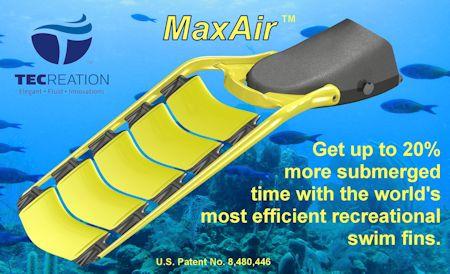
Inventing is a multi-faceted process. The idea is only the first step and is likely the easiest step. Once your idea is conceived the next step is determination of its originality. With originality established and you have established your idea is economically viable (by market analysis and a business plan) you would normally start making a prototype to prove your concept. To help you understand the simplicity and complexity of prototyping we will follow the process used to develop the MaxAir (tm) swim fin. We will also talk about the purposes of different types of prototypes. Every prototype is a learning experience which makes every prototype a good one.
The Sketch
The MaxAir ™ swim fin was conceived in a flash of inspiration in 2006 when I realized the thrust created by swim fins could be created using the same principles as used in airplane wings. I quickly sketched the image from my head and dated it.  - The first prototype is usually a drawing
This was prototype 1. Although it was only a sketch it embodied the major components of the concept. It had multiple wing shaped vanes on rubber hinges allowing them to rotate back and forth during the up and down strokes of the kick letting water flow over both sides of the vanes to create lift like an airplane wing.
A sketch prototype is certainly one of the easiest to make. It serves multiple purposes including identifying design difficulties, presentation of the concept to others, and documentation of the process.
The sketch helped identify possible prior art during my initial patent search. I found the multiple airfoil concept was not new. It was first introduced as US Patent 107,377 in 1870 as a vibrating propeller for a ship (before the screw propeller)  Prior art can turn up in anything
There were several other inventions which looked very much like my concept but were much more mechanically complex.
With confidence my rubber hinges (which I could not find) would lead to patentability it was time to make a "geometry study" or "mechanical study" prototype. These prototypes are simply to assist in solving some of the geometric problems
Geometric Study
The first physical prototypes of the fin was made of paper. 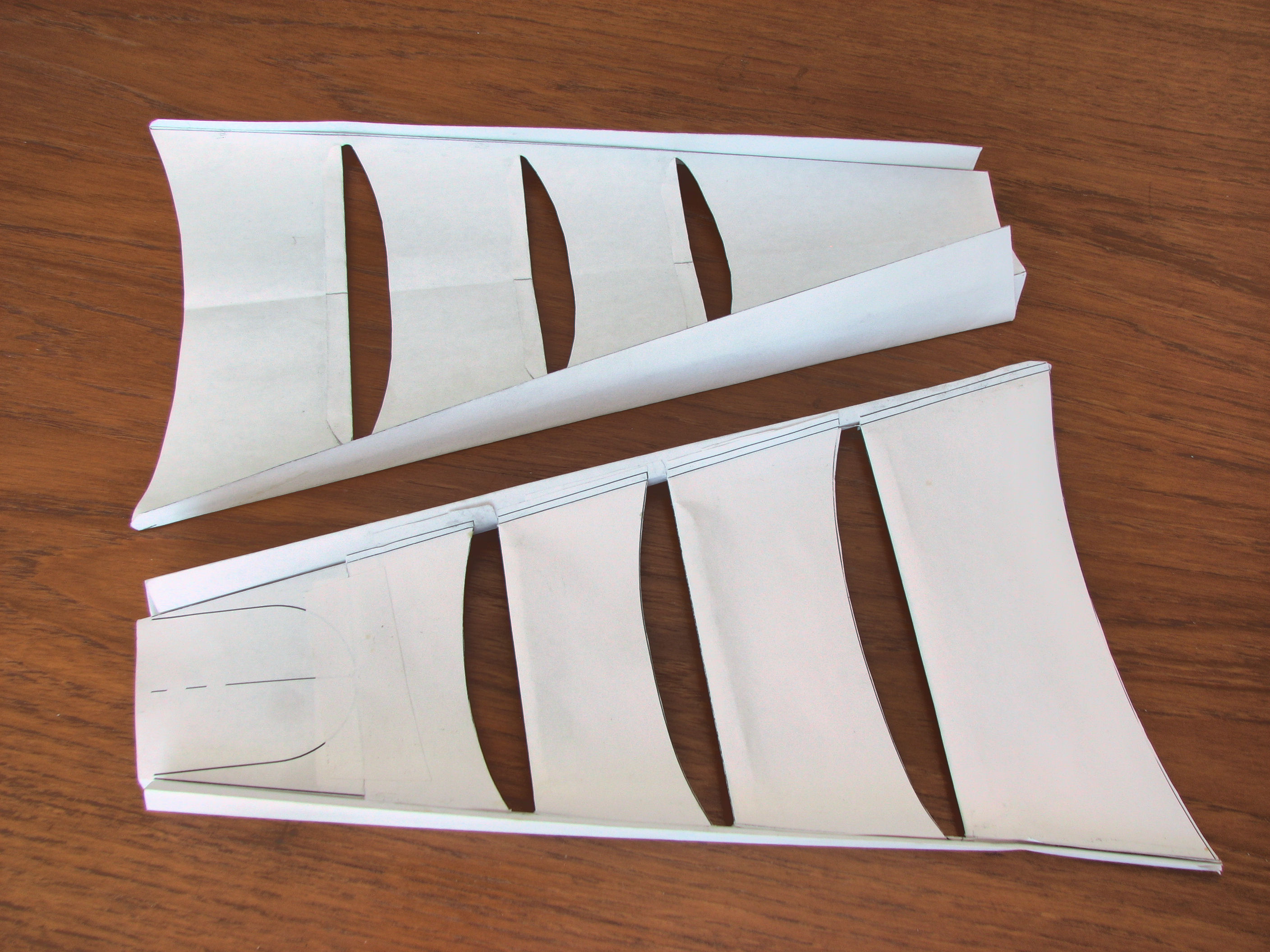
This may seem odd since fins are supposed to be used in water. These were simply for the purpose of testing how thin material may be employed to attain the geometric goals. While these were not glamorous nor full size they were made in a few minutes and illuminated some of the problems I would have with sheet material.
We must be aware that each prototype serves a specific purpose and it only needs to be made for that purpose. As inventors we want to see our vision in its final form as soon as possible. That seems to be a show stopper for many inventors since they are not necessarily good fabricators. Breaking down the problem into small steps can actually move us forward faster (and more economically) than attempting to materialize all of invention's qualities in the first try.
Proof of Concept
The US Patent office no longer requires working models of inventions but investors, for the most part, do. As an inventor you should also require some proof your concept will actually work. This is where the Proof of Concept prototype comes in. These are normally not pretty. Their purpose is to determine if the idea will or will not work. They do not have to look much like the final product but they need to provide the function of the invention. When dealing with electronic prototypes they are usually much larger than the final product and may not have a container of any sort. Each component is usually crude and inexpensive.
Prototypes do not have to be pretty
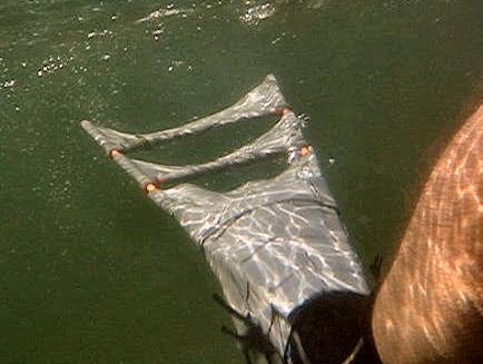
The parts for my first "proof of concept" all came from the hardware store. It was made of PVC shower pan liner and fiberglass driveway markers. I only made one of these and the next few iterations. Testing was done with the test fin on one foot and a conventional fin on the other to save time and cost. At this stage the fins were performing at only about 80% of that of conventional fins but given the crudeness there was room for improvement. Although the major efficiency improvement I sought was not realized, these gave me the encouragement to test a more expensive and time consuming prototype with adjustments based on the initial tests.
Over a year of spare time fin building and testing and 10 more prototypes to get to one which matched the performance of conventional fins. Each version was more complex and streamlined and the thin sheet vanes were replaced with actual airfoils (hydrofoils) to kick up the efficiency. 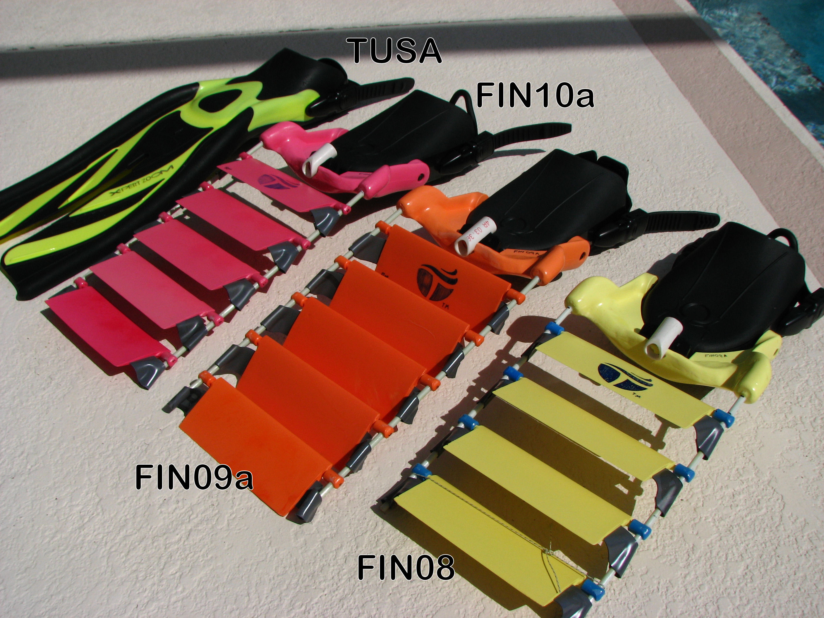 Three more prototypes and the competition
There was still a lot of drag created by the clunky design. Notice the fins in this group still have pin and socket hinges.
CAD Prototypes
The earlier prototypes made it clear I was on the right track but the new designs needed more precise and complicated shapes. The next physical prototypes were to be an order of magnitude more difficult to fabricate and more costly. Also the testing of the rough prototypes showed that, with the appropriate refinements, the concept was feasible and a patent should be filed. CAD, or Computer Aided Design, prototypes were helpful here because they allowed me to refine my design and create patent drawings at the same time.
I initially used AutoCAD to build some "looks like" digital models but found it was quite difficult to make modifications to the design. To keep costs low I purchased Alibre CAD (now Geomagic), a 3D CAD program, which allowed more flexibility when changing designs. It is a parametric program which means all the parts of the model are related to each other through intelligent dimensions. When I changed one dimension the rest of the model would update itself to accommodate the change. Alibre CAD works very well for geometric shapes but is a bit limited when it comes to the free form shapes needed for my fins. The complexity of my design soon exceeded the capability of Alibre CAD and I had to switch to Solidworks.
Solidworks is a robust 3D parametric program which is used by most manufacturers and fabricators. No doubt it is an expensive program costing about $10,000 depending on the feature set purchased. One feature I found to be of particular assistance was FEA, Finite Element Analysis. FEA allowed me to define the material my fins were made of then I could mathematically apply working loads to them to determine where the weak points will be. With each test I could go back and modify the model and test again. After spending a week to make the original model I was able to test over twenty variations in just a few days. 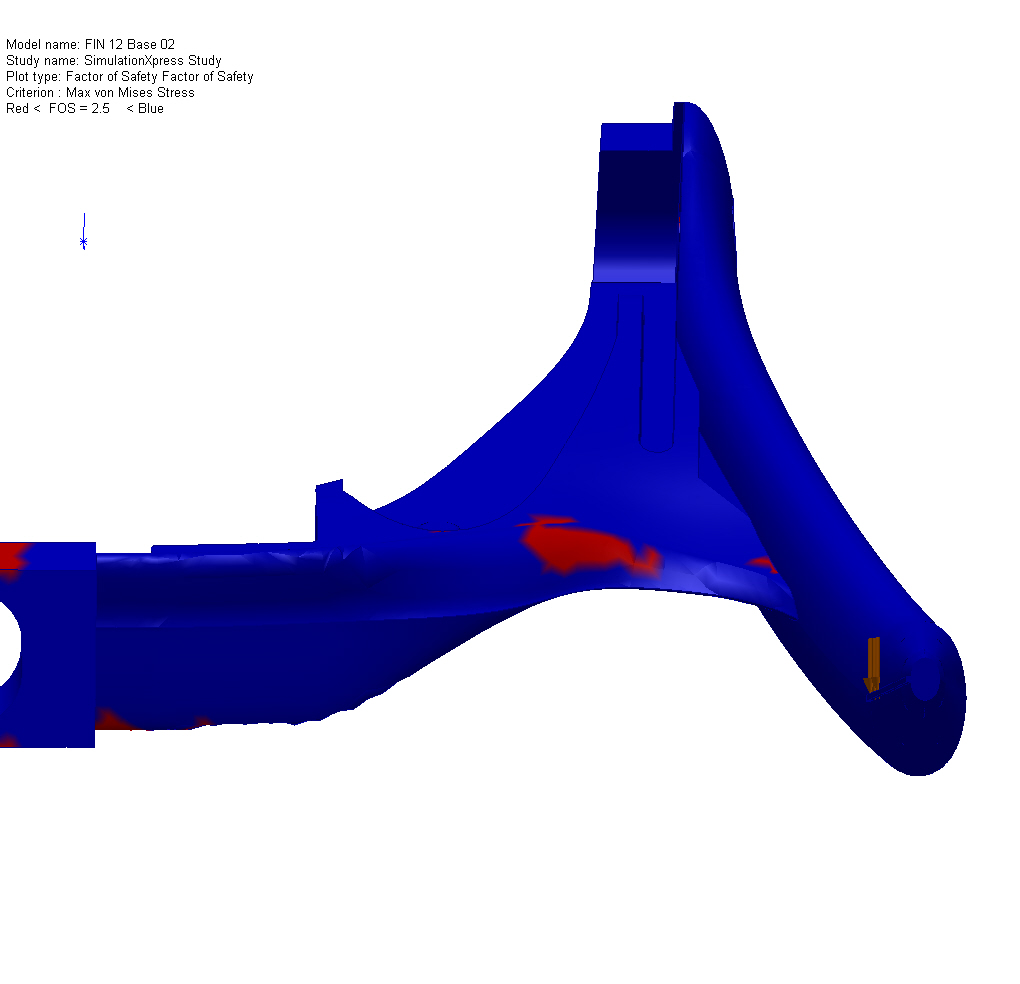 Finite Element Analysis in Solidworks shows likely failure points in red.
The creators of Solidworks, Dassalt Systems, offers a free 2D CAD program called DraftSight which works very much like AutoCAD if you are working on two dimensional projects. Google Sketchup also has a free version of 3D CAD. While it is easy to learn and use it is limited in its diversity. If you are working with geometric shapes this is a very good place to start learning 3D CAD.
Refined Functional Prototypes
With a rigorously computer tested CAD prototype in hand it was possible to get back to the physical prototypes. Most 3D CAD programs can export *.STL files. Sterolithography files are simplified versions of the CAD files which are used by most 3D printing devices which are also known as rapid prototyping machines. I sent the .stl files for my fins to a local rapid prototyping company and a few days and a several hundred dollars later I had new physical parts for my fins. There are rapid prototyping companies all over the web but I recommend you find a local company to do your printing for you. They are usually less expensive and much easier to talk to. By offering to pass out their business cards at my local inventors council I was able to get some discounts on my printing. I never asked for the discounts I just offered to pass out their cards.
Those shiny new parts were nice but they were not made of the correct material for my fins so I had to learn urethane plastic casting. (That process will be another article.)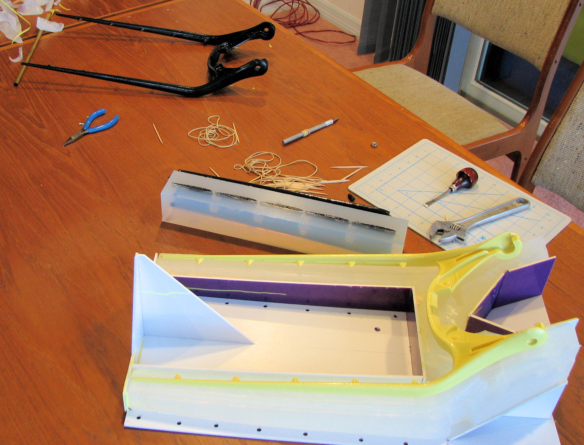 Rapid prototype parts (black) and silicone molds made from them.
To get my fins made of the correct material I used my printed parts to make molds then filled the molds with polyurethane plastic. The molds were reusable so I was able to create many prototypes from that one set of printed parts. Prototypes 12 through 45 were all made in this fashion. Most of the variation between prototypes was changes in the material. I learned much more about the characteristics needed. Smooth-On.com has an extensive library of polyurethane plastics which vary from soft rubbers to extremely hard. Of course testing was done and phenomenal results were attained. The fins fabricated near the now patented design produced air savings of up to 50% over the competition. Now I have analytic proof my product works better than the competition.
Several of the prototypes were sent to major fin manufacturers for testing for licensing. They agreed my fins performed better but declined to license because it would cannibalize their own product line. The lesson here is to look for a company where your product would create a product line extension rather than a product replacement.
Analytic Prototypes
Not all prototypes need to be the complete invention. Analytic prototypes can be just a small part of your device which is giving you trouble. For the main support rails of my fins are a case in point. All the testing to this point has been performance testing but the production version will be made of a different material. A material change could substantially change the characteristics of your product too. Polyurethane casting plastics are great for low cost prototyping and testing but they do not have the durability and heat resistance of injection molded polypropylene. Analytic prototypes can be used to calibrate the actual stresses placed on your product which will be needed to design for the actual production material.
The earlier versions worked well but under severe loading broke too often. There is little stress strain data for polyurethane plastic so I had to build a testing apparatus and collect that data. I then used it to design a mathematical material for Solidworks by loading the same shape on the computer as I did in real life and adjust the parameters until the same deflection was attained. I then used this material for the pre-production model and was able to find and fix the failure points before making the next rapid prototype. 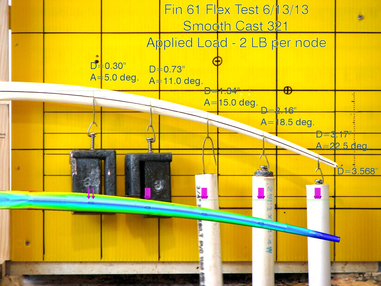 loaded real model with Solidworks model below showing stress levels
Pre-Tooling Prototypes
The pre-tooling prototype is intended to test the fit and function of your design when it is adjusted specifically for the constraints of injection molding or whatever manufacturing method you end up using. Once all the field testing was done it was necessary to convert all that gained knowledge into an actual product. Based on some cursory load testing of the functional prototypes I "guessed" the load for design. The testing of the pre-tooling prototype showed me I had solved the strength problem but was way high on my load "guess" which created the need for another round of functional prototypes. This is where I am today.
Pre-Production Prototypes
Most products require some sort of tooling, or molds, to make the plastic parts. This process is a highly technical and costly procedure usually done by the company which is contracted to manufacture your product. (We are planning on using crowd funding to raise the tooling cost using the fins as the reward. All those who have seen the fins are looking forward to it.) Due to the flexible nature of my fins I know I will have to test the first run of the polypropylene injection molded parts to determine if everything interacts correctly then adjust the tooling accordingly. 
CAD models are also very useful for photorealistic renderings of your product.
Since FEA is quite costly and only produces an estimate of the actual product performance a good practice is to under size the tooling then test the resulting product. Cutting a little more material out of the tooling if the part breaks in testing is easier than it is to fill the tool back in if the part is too strong. Using two or three re-cuts of the tool with testing between should get you to the final product configuration without undue expense. For rigid products this set of prototypes is mostly for a final test of the fit and function. When you get through this step you will actually have a production product.
As you can see prototypes are many and varied. You may not have to move through all these steps for your product but now you can see that prototyping is an evolutionary process. Your first prototype will not be your last. Don't lock yourself into only wanting to make your production version of your product. That will likely stifle your entire development process both intellectually and financially. It is interesting to note that most manufacturers completely redesign a licensed product to add their brand feel to it regardless of how well the product was designed. When you sell your idea expect it to be changed. In the mean time get started prototyping.
David Woods is a Professional Engineer and 2006 founder of TECreation Development LLC, a product development company based in Florida. They specialize in improving the efficiency of products through elegant, fluid, innovation. Watch for the announcement of the crowd funding of the fins and contact him through the website www.TECreationDev.com.
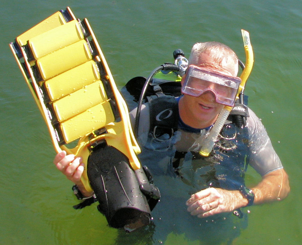
The author with successful prototypes in Lake Conway